- Help Center
- Ansys HFSS
-
Getting Started With Ansys
-
Ansys Installation
-
Licensing
-
Ansys Mechanical
-
ANSYS AEDT
-
Ansys Maxwell
-
Ansys HFSS
-
Ansys CFD
-
CAD
-
Meshing
-
LS-Dyna & LS-Prepost
-
SpaceClaim
-
Ensight
-
Ansys Lumerical
-
Zemax
-
Discovery
-
AUTODYN
-
Workbench
-
Ansys EMC Plus
-
SIwave
-
CFD-Post
-
Ansys Sherlock
-
Q3D
-
Ansys 3D Layout
-
Fluent Meshing
-
Thermal Desktop
-
Icepak
-
Ansys Icepak
-
Twin Builder
-
Fluent
-
AEDT Circuit
-
EMA3D
-
Linux
-
Optislang
-
Motor-CAD
-
Ansys CFX
Internal Wave Ports in HFSS
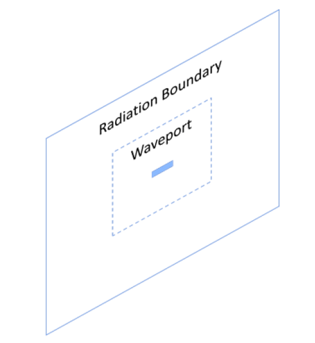
Wave port in contact with radiation boundary the usual case. This is what you see.

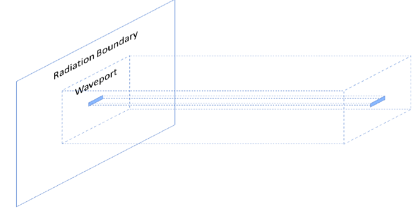
This is how HFSS treats it. HFSS calculates modes that can propagate in this semi infinite waveguide with cross section same as enclosed by waveport boundaries. The default boundary of the outer surface of this waveguide is PEC if wave port touching Radiation Boundary, else it’s the same as the boundary it’s touching.
Note: The default boundary condition can be changed to Radiation in Setup.

- Here waveport is located inside the radiation box hence not in contact.
- Need a way to define the boundary for the semi infinite waveguide that feeds through the waveport.
- WORKAROUND for internal waveport
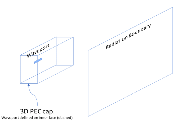
- Add a thin slice of PEC onto the waveport. This will provide the PEC boundary to our imaginary waveguide. It will also shield from any reflections into the port. One can use any good conductor.
- When assigning an internal wave port, HFSS will automatically prompt to create a 3D PEC cap.

-2.png?height=120&name=Ozen%20Long%20-%20Back%20(1)-2.png)