- Help Center
- Ansys HFSS
-
Getting Started With Ansys
-
Ansys Installation
-
Licensing
-
Ansys Mechanical
-
ANSYS AEDT
-
Ansys Maxwell
-
Ansys HFSS
-
Ansys CFD
-
CAD
-
Meshing
-
LS-Dyna & LS-Prepost
-
SpaceClaim
-
Ensight
-
Ansys Lumerical
-
Zemax
-
Discovery
-
AUTODYN
-
Workbench
-
Ansys EMC Plus
-
SIwave
-
CFD-Post
-
Ansys Sherlock
-
Q3D
-
Ansys 3D Layout
-
Fluent Meshing
-
Thermal Desktop
-
Icepak
-
Ansys Icepak
-
Twin Builder
-
Fluent
-
AEDT Circuit
-
EMA3D
-
Linux
-
Optislang
-
Motor-CAD
-
Ansys CFX
How to find the angular location of far-field peak values in HFSS
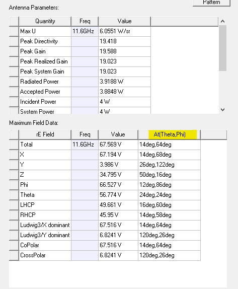
The Antenna Parameters dialog window contains the theta and phi angles which correspond to the peak beam value for many common polarization definitions.
When simulating a steered-beam antenna array, the user often desires to find the angular location of the far-field beam peak value . HFSS can automatically report the corresponding phi and theta angles for the far-field beam peak value.
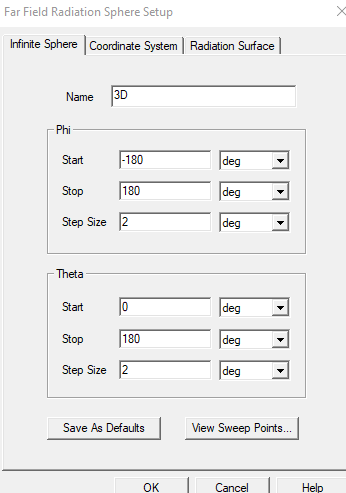
This information is found in the Antenna Parameters dialog window. To show the Antenna Parameters, the user must first create a Far Field Radiation Sphere and specify the Phi and Theta angle ranges and steps:

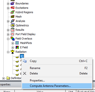
Then the Antenna Parameters dialog window can be opened by right-clicking on the Far Field setup in the Radiation section of the Project Manager:

The Maximum Field Data table has a column named At(Theta,Phi) which shows the location of the peak value for many commonly used polarizations. These angles are the theta and phi values that correspond to the peak value in the far-field beam.

-2.png?height=120&name=Ozen%20Long%20-%20Back%20(1)-2.png)