- Help Center
- Ansys HFSS
-
Getting Started With Ansys
-
Ansys Installation
-
Licensing
-
Ansys Mechanical
-
ANSYS AEDT
-
Ansys Maxwell
-
Ansys HFSS
-
Ansys CFD
-
CAD
-
Meshing
-
LS-Dyna & LS-Prepost
-
SpaceClaim
-
Ensight
-
Ansys Lumerical
-
Zemax
-
Discovery
-
AUTODYN
-
Workbench
-
Ansys EMC Plus
-
SIwave
-
CFD-Post
-
Ansys Sherlock
-
Q3D
-
Ansys 3D Layout
-
Fluent Meshing
-
Thermal Desktop
-
Icepak
-
Ansys Icepak
-
Twin Builder
-
Fluent
How to define Wave Ports for Quasi-TEM Transmission lines in HFSS Transient?
Problem/Description: Define wave ports for quasi-TEM mode Transmission lines in HFSS Transient
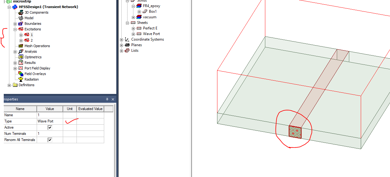
Generally, wave ports in HFSS transient can be defined for transmission lines wherein pure TEM mode propagation exists (such as coaxial or stripline). For problems such as microstrip where the propagation is through two different media (air and dielectric), a quasi TEM mode exists. For this scenario, some special care must be take care (as shown below).
Solution:
Adjust the size of the port such that it is inside the dielectric as shown in Fig.1

Figure 1. Waveport settings for quasi-TEM transmission lines in HFSS Transient
-2.png?height=120&name=Ozen%20Long%20-%20Back%20(1)-2.png)