-2.png?height=120&name=Ozen%20Long%20-%20Back%20(1)-2.png)
This solution shows how to create a Perfectly Matched Layer (PML) termination for a circular waveguide in HFSS versions 2023R1 and later
Previous releases of HFSS allowed the user to draw a circle, select its face using Face Select mode, and create the PML object from the face. However, this method crashes HFSS versions 2023 R1 and 2023 R2 when it is applied to a circle . It does work correctly for rectangular and polygon faces. This behavior has been submitted as a defect to be corrected in a future release.
This article describes a workaround to create the PML termination by following the steps below. These steps are based on the instructions in the HFSS help manual section titled "Creating PML Boundaries Manually."
- Create the circular waveguide cylinder which will be used as the base object.
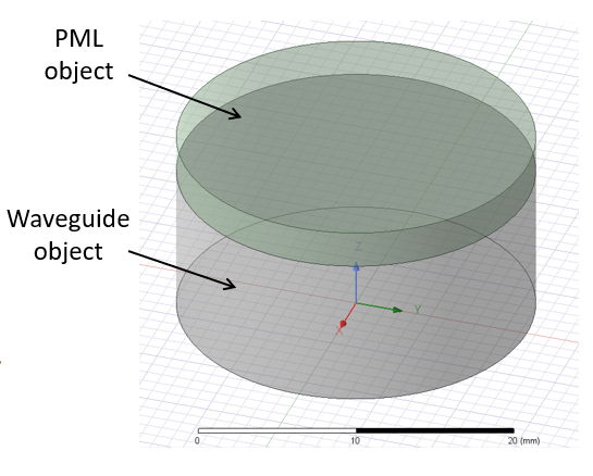
- Create a cover cylinder which will be used as the PML object. The cylinder name must begin with PML for HFSS to recognize it as a PML object. The image below shows an example circular waveguide below a PML cover cylinder.
- Select the cover cylinder and choose the menu item HFSS > Boundaries > PML Setup Wizard. This will open the PML Setup Wizard which consists of 3 pages to be completed.
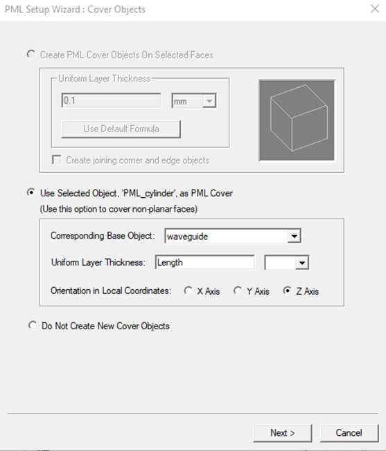
- On Page 1 of the PML Setup Wizard:
- Set the Corresponding Base Object to the waveguide.
- Set the Uniform Layer Thickness to a value which is at least 1/2 wavelength at the lowest frequency. It can also be set to a variable to allow a parametric sweep to study the effect of the thickness on the reflection coefficient.
- Set the Orientation in Local Coordinates to the appropriate axis of the waveguide.
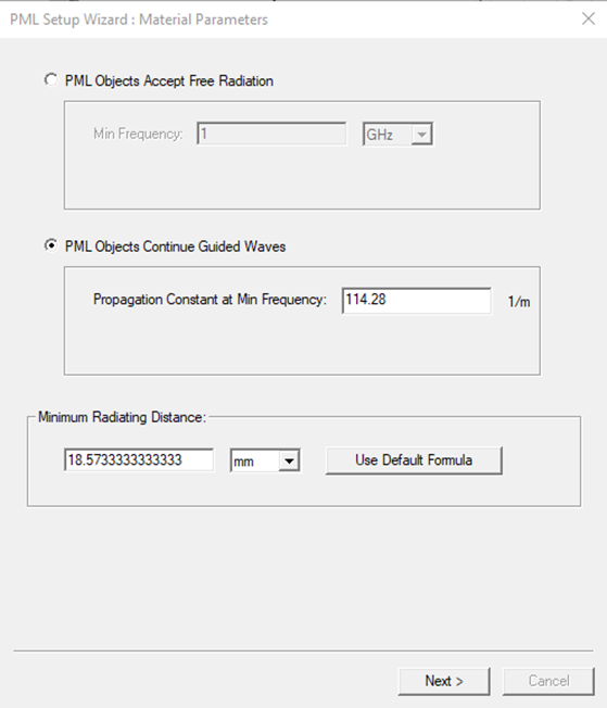
- On Page 2 of the PML Setup Wizard:
- Choose "PML Objects Continue Guided Waves".
- Set the Propagation Constant at Min Frequency to the phase constant (beta) value for the desired waveguide mode. This value will be used to determine the appropriate material properties for the PML termination. You can obtain the beta value from a ports-only solution by viewing Gamma in real/imaginary format and noting the imaginary component. The image below shows the use of a beta value of 114.28 rad/meter.
- Leave the Minimum Radiating Distance to the default value.
- On Page 3 of the PML Setup Wizard:
- Review the summary information and select Finish to close the wizard.
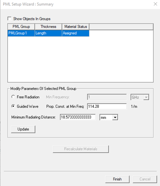
- Review the summary information and select Finish to close the wizard.
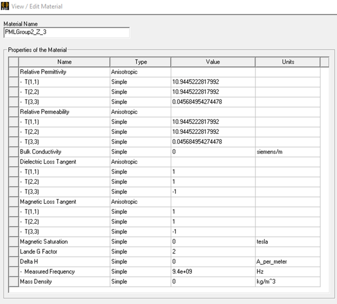
The material properties used in the PML termination are automatically created using the settings specified in the PML Setup Wizard. Anisotropic properties are used for the relative permittivity, relative permeability, dielectric loss tangent, and magnetic loss tangent. The values provide a lossy termination for the incoming wave. The image below shows example material properties:
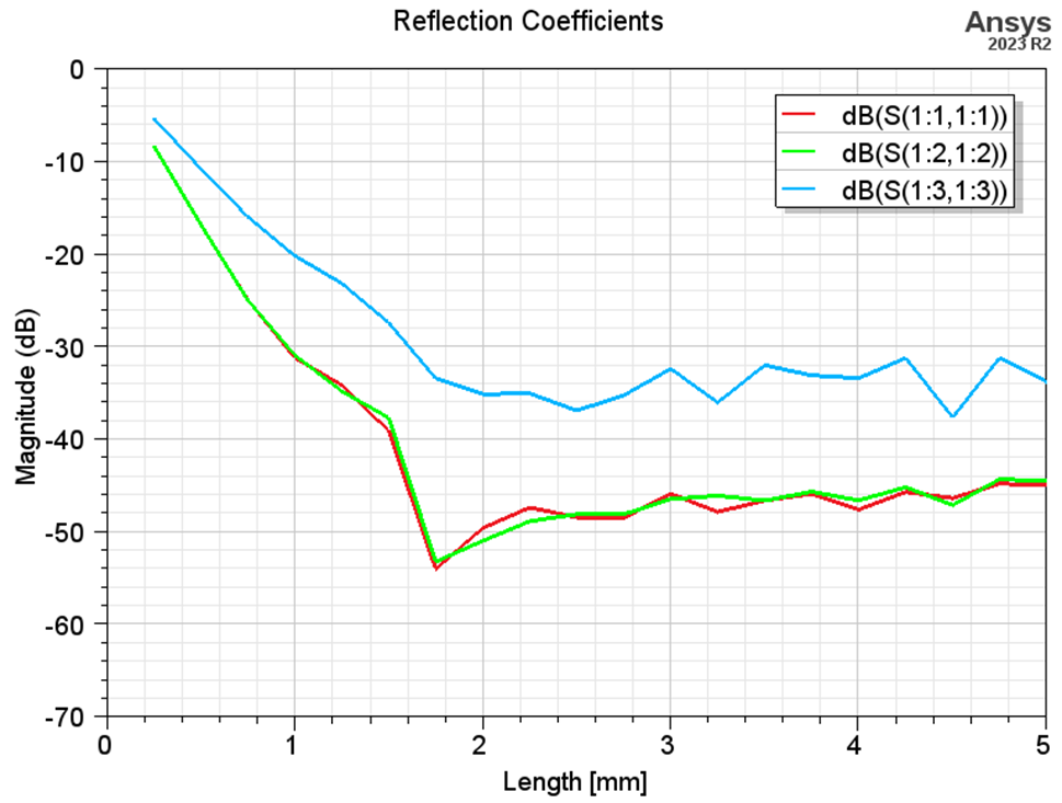
The PML termination is intended to accept the incoming wave from the waveguide with a very low reflection coefficient. The image below shows the reflection coefficients for the first 3 modes of an example (which are a pair of degenerate TE11 modes and the TM01 mode) versus the PML cover thickness. Once the PML termination is sufficiently thick (which occurs at approximately 1.6 mm for this example solution frequency), the reflection coefficient for the TE11 modes is lower than -45 dB and the reflection coefficient for the TM01 mode is lower than -30 dB. This means that more than 99.9% of the incoming power is accepted by the PML termination.